
01
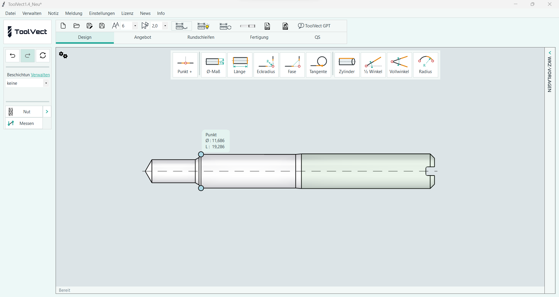
Sketch the contour
Add and move nodes with the mouse. Start with a rough sketch.
For tool manufacturers and tool users
From tool contour to dimensioned drawing: develop drills, milling cutters, reamers and countersinks in one app.
Free personal demonstration: online or on site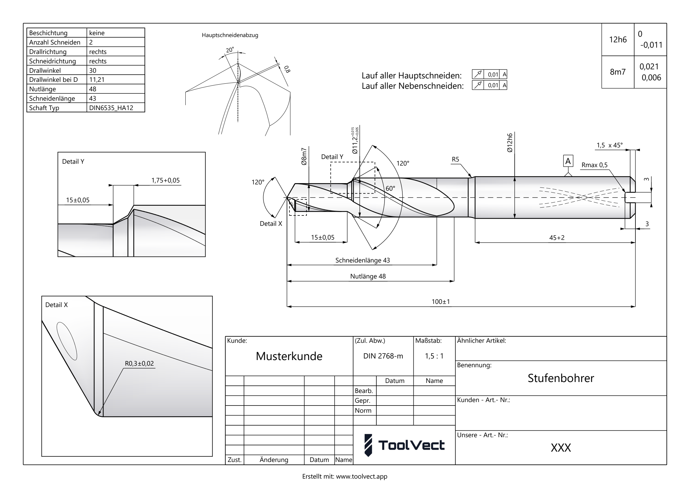
Working with ToolVect
One tool, three steps. Turn a rough sketch into precisely dimensioned geometry and then a drawing sheet.
Add and move nodes with the mouse. Start with a rough sketch.
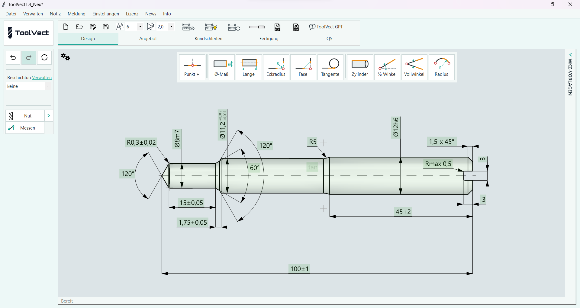
Enter dimensions, tolerances, radii and chamfers. ToolVect calculates the contour from your parameters.
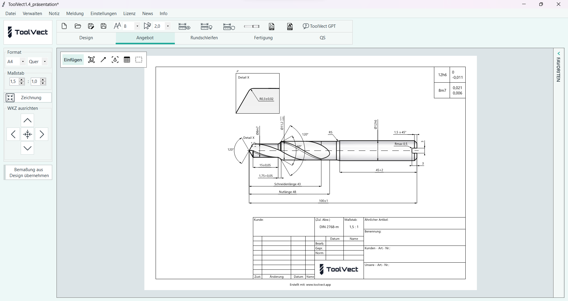
Place the tool on a drawing sheet. Arrange quotation and production drawings independently.
Product screenshots show the German software interface.
Change parametric dimensions and recalculate the contour.
Save, reuse and exchange tool templates.
Export DXF contours and prepared Excel inspection reports.
ToolVect / Windows
Start a free 30-day trial with all features immediately after installation. No licence key is needed for the trial.
Current installer
Windows 10 / 11 · 64 Bit
Downloads the ToolVectSetup.exe installer.
Privacy policy
ToolVect / Features
Tools for design, drawing, cylindrical grinding and quality assurance.
Draw the tool contour directly with the mouse.
Add and move nodes to create the outer contour. Start with a rough sketch, then define the geometry with parametric dimensions. ToolVect calculates the node positions precisely at the centre of the tolerance range and aligns the geometry.
Define dimensions, tolerances and transitions parametrically.
Set nominal dimensions, tolerances, chamfers, radii and cylindrical elements at the nodes. ToolVect positions the contour and detects overconstrained or conflicting dimensions. Dimensions remain editable parameters; changing them recalculates the contour.
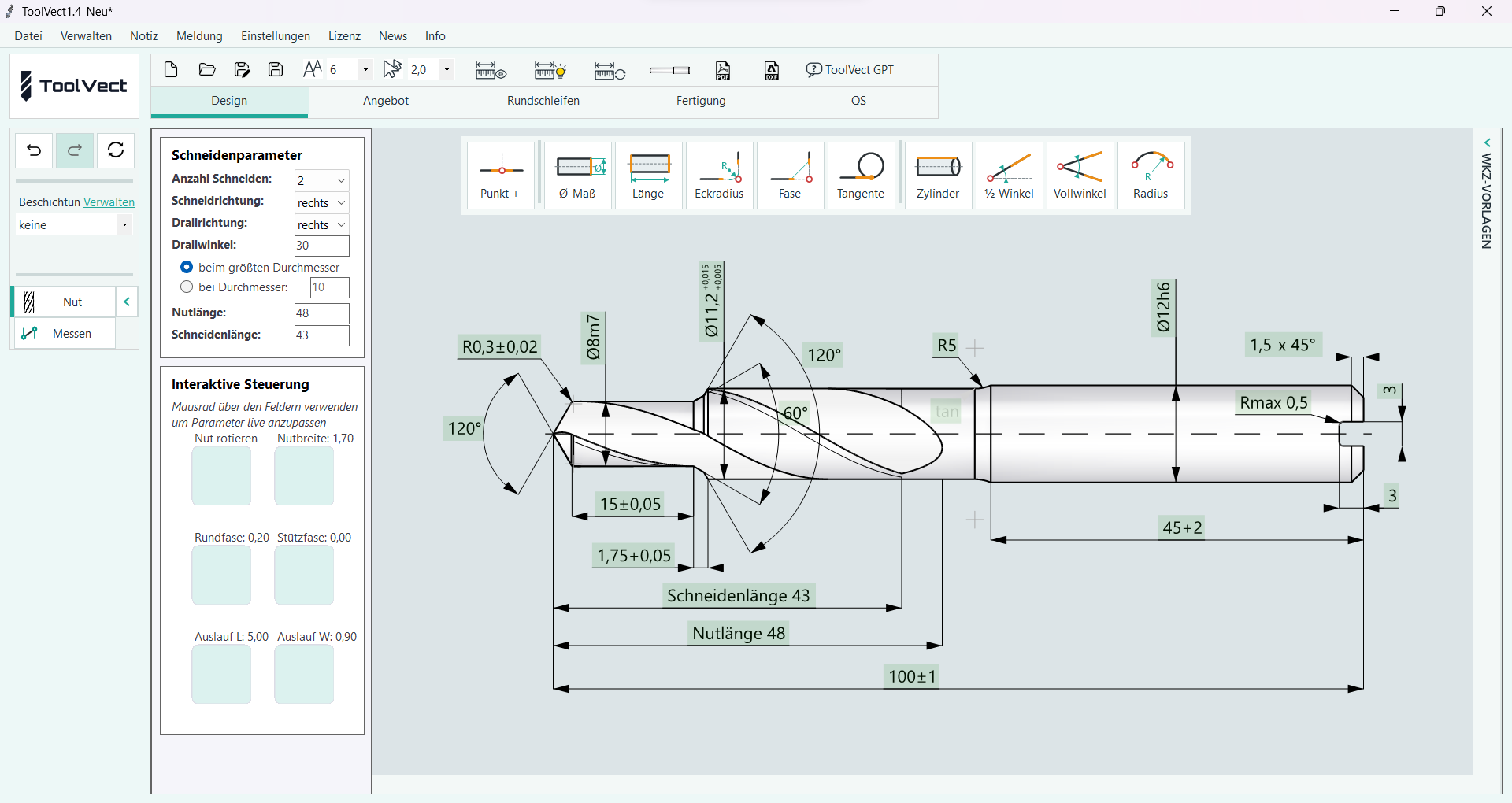
Adjust flute parameters with immediate visual feedback.
Set flute parameters and position in the flute panel. Use the mouse wheel to adjust values and see the changes directly on the tool, without switching between views.
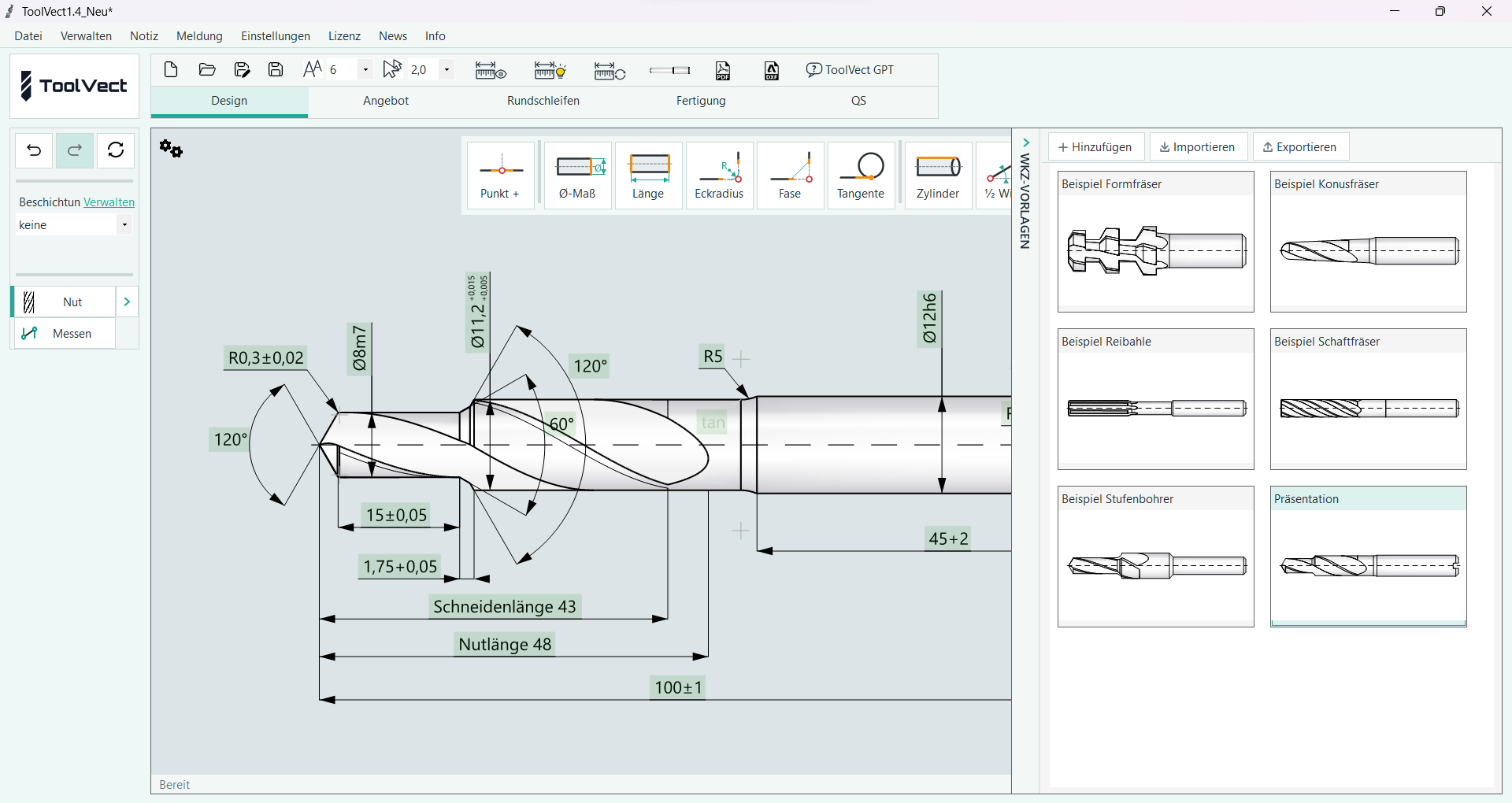
Reuse proven designs and share them with your team.
Save and name tool templates locally on your computer. Drag a template into the drawing area to change dimensions, add steps or insert corner radii. Import and export templates to exchange them with colleagues or other sites.
Create separate drawings for customers and production.
Choose the drawing sheet format, complete the title block and set the scale. Add enlarged detail views. Quotation and production drawings have the same tools but can be arranged independently, so internal manufacturing details remain on the production sheet.
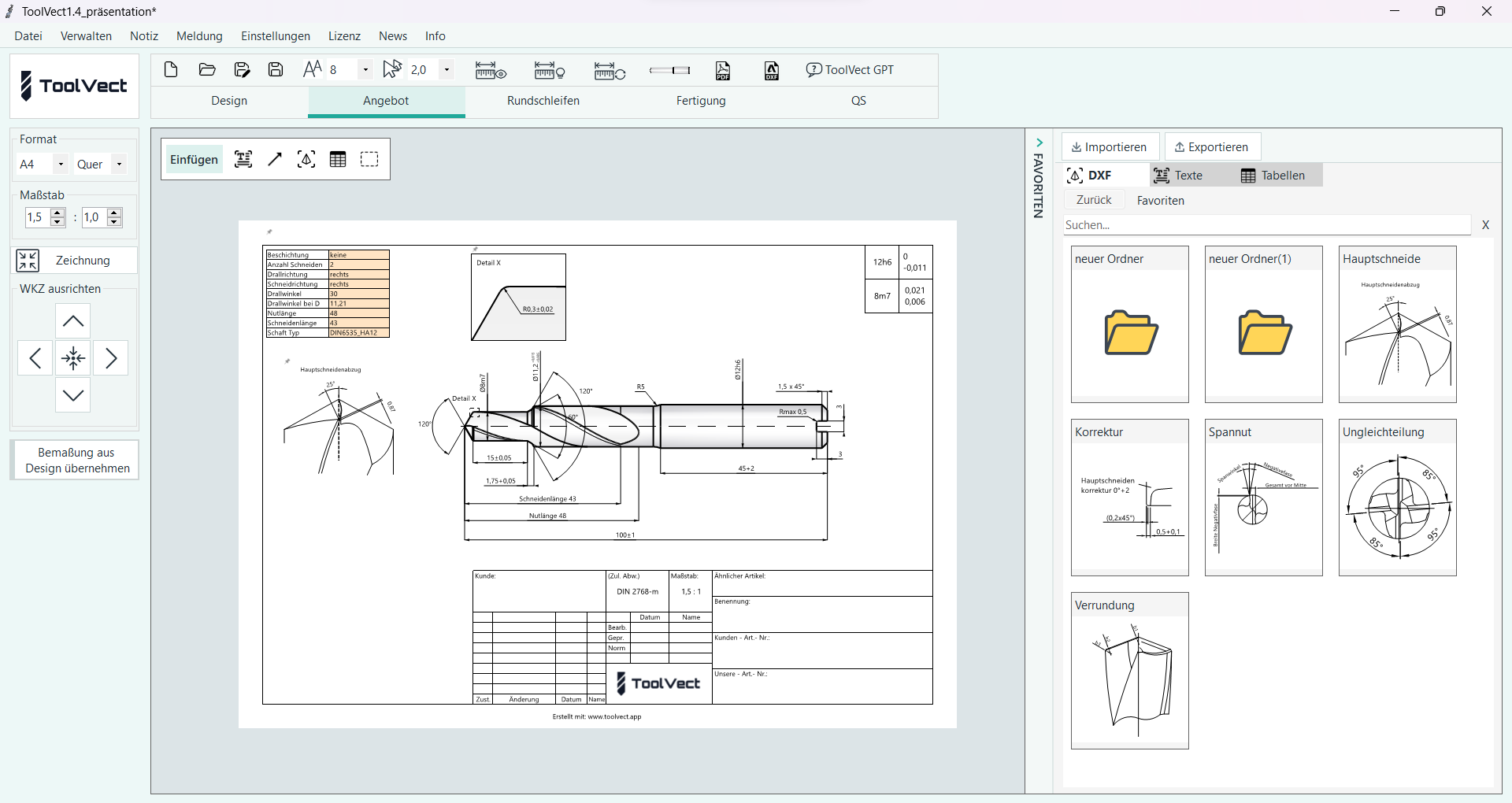
Combine text, DXF objects and tables on the drawing sheet.
Place and format text freely. Import DXF files by drag and drop or through a dialogue; edit their text, position and scale. Tables support spreadsheet-style formulas and app variables such as the number of cutting edges. Save objects as favourites and reuse, import or export them.
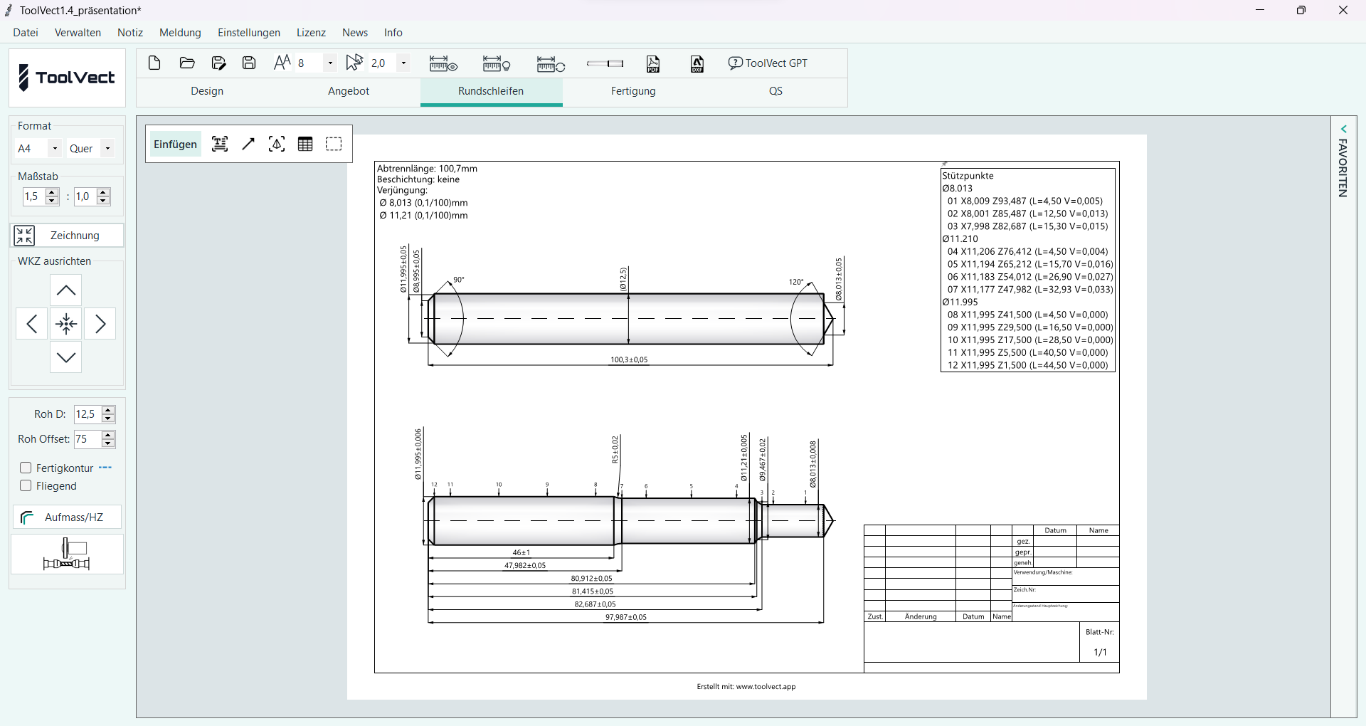
Derive grinding and blank drawings from the contour.
Dimensions are calculated at the centre of the tolerance range, taking coating thickness into account for relevant diameters. Lengths are dimensioned from the origin, with additional support points for cylinders and tapers. The current version supports grinding between centres. Chuck-mounted grinding is planned for a future update.
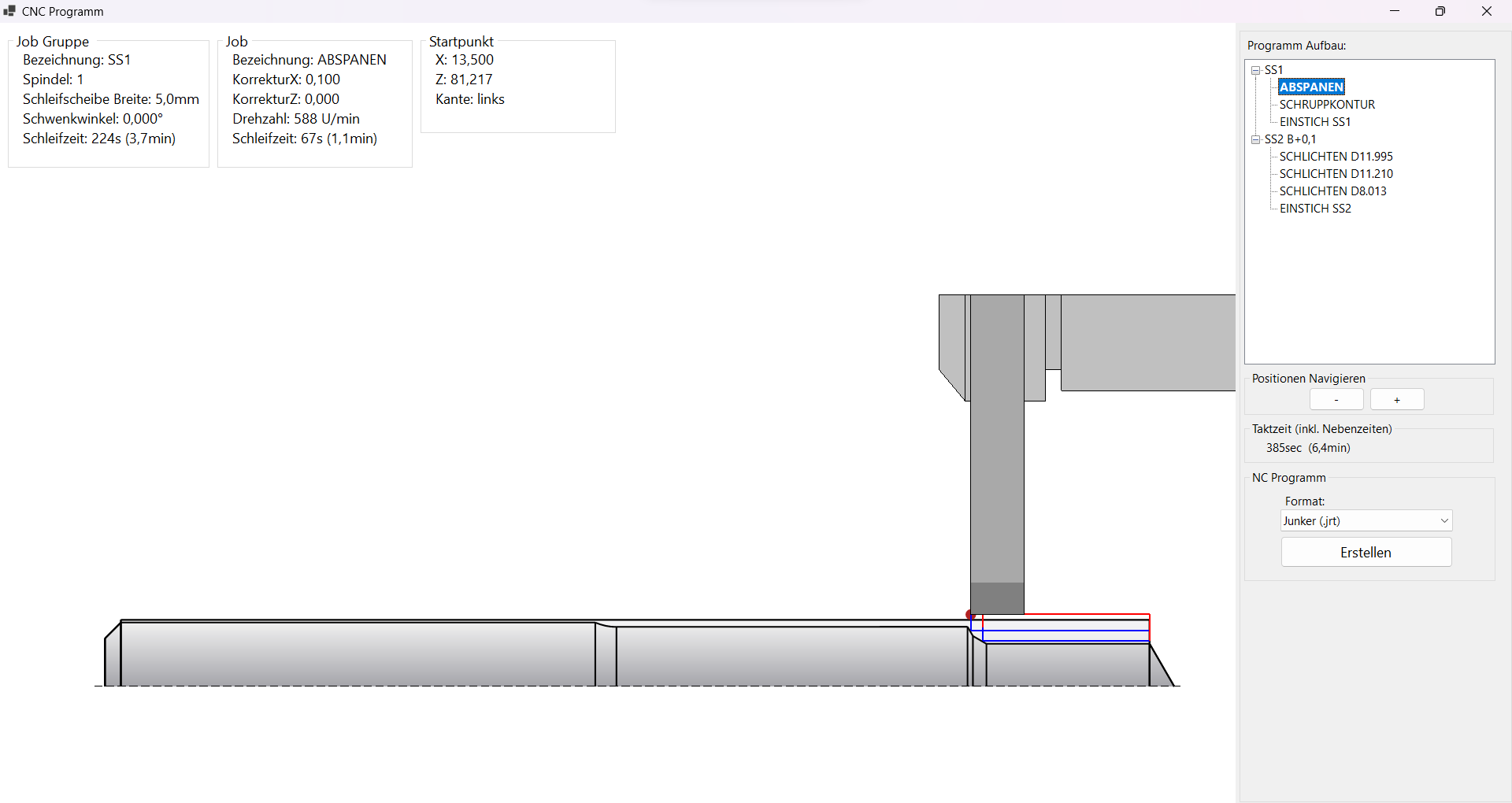
Generate NC code and preview machine movements.
Create an NC program and estimate grinding time. Visualised machine paths help you check the machining strategy. Current output supports import into JUNKER Juwop/PR. Fanuc, Siemens and customer-specific formats can be implemented. Automatic feed calculations based on material removal rates and diameter-dependent cutting depths are planned.
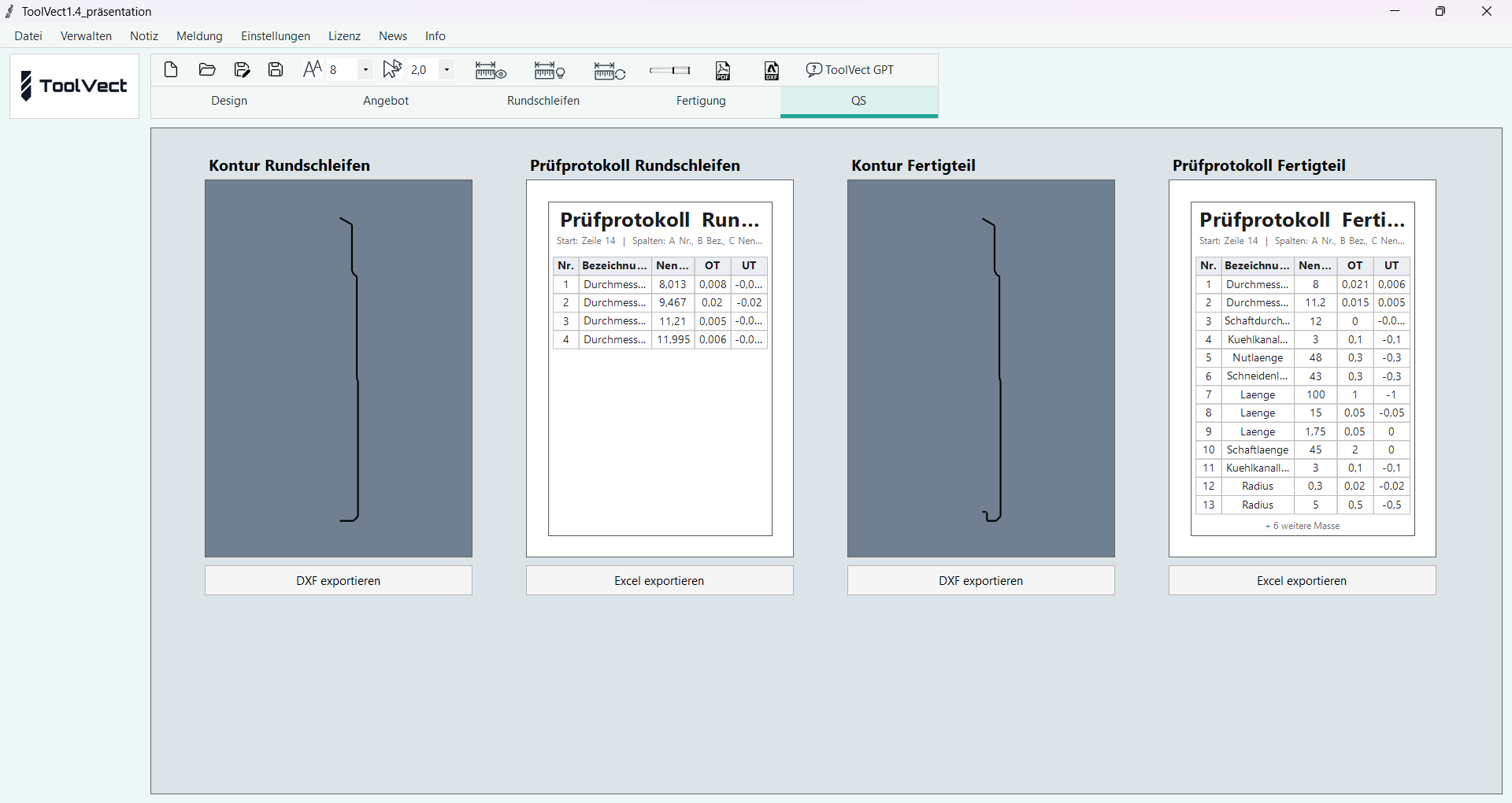
Export contours for inspection and measurement.
Export DXF files of the grinding and finished-part contours, drawn at the centre of the tolerance range. Generate prepared Excel inspection reports with target values. Additional exports and customer-specific interfaces can be implemented on request.
The following items are development plans, not features promised for the current release.
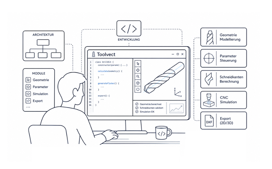
Further automation for tool manufacturing.
Planned developments include 3D workpiece models, integrated cost calculation, AI-assisted cutting and tool parameters, additional grinding operations, and further export formats and interfaces. These are development plans, not features promised for the current release.
ToolVect / Contact
We will introduce ToolVect online or at your premises, free of charge and with no obligation. Discuss your application and ask your questions.
Request a personal demonstrationOnline or at your premises. We will arrange the format and date with you personally.